Recent activities are posted on our wiki page
https://vega-wiki.oca.eu/foswiki/bin/view/Main/WebHome
Functional Analysis and product breakdown
We can break down the VEGA instrument into two different sub-systems:
- The Interface Optics (Acronym: IOP)
- The Spectrograph (Acronym: SPE)
The main functions of the Interface Optics sub-system are to:
- inject the beams coming from CHARA to VEGA
- adjust the pupil location (see Annex A)
- reduce the size of the beams (from 3/4 inches to 5 mm)
- configure the beams at the entrance of the spectrograph (vertical separation of 10mm)
- provide artificial beams to calibrate and align the instrument
- adjust the optical path difference (the zero OPD plan could be the same as the visible CHARA combiner one)
Due to the important spectral dispersion of the VEGA instrument, it is not necessary to correct the chromatic image shift caused by the atmospheric refraction. In addition, the fact that the main part of the optical path between the telescopes and the instrument is inside vacuum tubes allows to avoid the use of a chromatic OPD compensator (see Annex B).
The main functions of the Spectrograph sub-system are:
- to combine the beams
- to disperse the fringe signal
- to optimize the fringe sampling
- to select the polarization
The following diagram shows the different modules which compose the sub-systems:
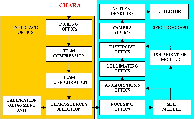
Sub system decomposition of VEGA
The following table summarizes the different functions of each module:
|
SUB-SYSTEM : INTERFACE OPTICS (IOP) |
||||
|
MODULE NAME |
ACR. |
COMPOSITION |
M# |
FONCTIONS |
|
Picking Optics |
PGO |
Set of 4 periscopes |
* |
Injects the beam coming from CHARA into VEGA Avoids beam vignetting due to the mounts of the optical elements of the CHARA visible combiner |
|
Beam Compression |
BCP |
Parabolic and spherical mirrors |
Reduces the beam size (0.75 inches → 5 mm) Adjusts the pupil location Adjusts the ZOPD |
|
|
Beam Configuration |
BCF |
Set of 4 flat mirrors |
Configures the beam (with a beam separation of 10 mm) Puts the beam in a vertical configuration |
|
|
Calibration and Alignment Unit |
CAU |
Artificial sources (spectral and halogen lamps, laser) Collimator Mask |
* |
Produces light for internal alignment and for the co-alignment between the instrument and CHARA Produces light for the calibration (flat-field, distortion grid, spectral calibration, …) |
|
CHARA/Sources Selector |
CSS |
Beam splitter Flat mirror |
* |
Feeds the spectrograph with the internal sources or with the beams coming from CHARA |
|
SUB-SYSTEM : SPECTROGRAPH (SPE) |
||||
|
MODULE NAME |
ACR. |
COMPOSITION |
M# |
FONCTIONS |
|
Focusing Optics |
FOC |
Parabolic mirror |
Produces an image at the spectrograph slits level |
|
|
Slit Module |
SLM |
Slits |
* |
Selects a part of the image |
|
Anamorphosis Optics |
ANO |
2 cylindrical mirrors |
Optimizes the sampling (ratio 12 between the spectral and the spatial directions) |
|
|
Collimating Optics |
COL |
Parabolic mirror |
Collimates the beams |
|
|
Polarization Module |
POL |
Wallaston prism λ/4 blades |
* |
Allows to separate the 2 polarization directions |
|
Dispersive Optics |
DIS |
3 gratings |
* |
Disperses the light Selects between 3 different spectral resolutions (1700, 5000, 35000) |
|
Camera Optics |
DFC |
Parabolic and flat mirrors |
Produces a dispersed fringes image at the detector level |
|
|
Neutral Densities |
NDN |
Neutral densities |
* |
Attenuates the flux |
|
Detector |
DET |
Detector |
* |
Detects the dispersed image |
Functional analysis of the different subsystems of VEGA.
Implantation
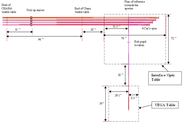
We have studied two possible implantations for the VEGA spectrograph. The first option was to remove the current CHARA visible table and to replace it by a larger one able to host the VEGA interface optic. In fact, this solution is really heavy for CHARA and do not minimize the number of reflexions for VEGA. We present here the preferred solution for the location of VEGA.
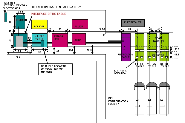
Details of the Zemax solution for the optic interface
The optic interface is separated into the pick-up mirrors installed on the CHARA visible table and a new optical table which will support the interface optics:
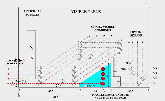
Side view of CHARA Visible Table
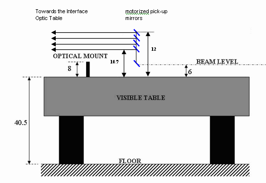
Top view of CHARA Visible Table
VEGA pick-up systems inside the CHARA visible table
We add motorized pick-up mirrors (periscopic system) in the CHARA visible table in order to pass above the mounts of the optical elements and to send the beams towards the Interface Optic Table.
On the following Figure, we present the current optical design of the interface optic system.

ZEMAX view of the Interface Optic Table of VEGA (side view)
ZEMAX view of the Interface Optic Table of VEGA (top view)
The new optical interface table will support the Beam Compressors (with compensation of OPD and pupil reimaging function) and the Beam Configuration modules. At the entrance of the table, the beams have a diameter of 0.75” and a horizontal separation of 3”. At the output of the Optic interface table, the four beams are vertically spaced, with a separation of 10mm and the beam size is 5mm. This table will also host the VEGA calibration and alignment sources.
The following figure presents different views of the optical system installed on the interface table:


Optical configuration of the interface optic. Side view (up), front view (bottom)
as seen from the CHARA beams before the pick-up mirrors.
